This started with a very simple thought: the solar panel is dead, the lights still work, so surely I can just power them from USB?
As it turns out, yes — but only after a few wrong assumptions, some relearning, and a helpful reminder that I am much rustier at soldering than I thought.
This is less a story about “here is the correct way to do electronics” and more a story about poking at a dead gadget, trying to understand how it works, and learning just enough to get it going again.
If you’ve done this sort of thing before, there are probably better ways to approach parts of it. If so, I’d genuinely be interested.
The Starting Point
I had a small pile of half-working Christmas lights. They were the cheap outdoor solar kind: little black controller box, tiny solar panel, rechargeable batteries, and a button that cycles through a handful of blinking modes.
The solar side had died. The LEDs themselves seemed fine.
That made me wonder: could I just run the whole thing from USB instead?
That sounded like it should be easy. It mostly was not. Or at least, not in the “five-minute fix” sense.
Opening The Box And Immediately Learning Something
Inside the controller box were three rechargeable AA batteries labelled:
NiMH AA 1.2V 400mAh
My first mental shortcut was: three batteries, so 4.5V.
That’s the kind of assumption that feels right until you look properly.
These weren’t ordinary alkaline AAs. They were NiMH cells, which sit at different voltages.
Roughly speaking:
- Nominal: 1.2V
- Fully charged: about 1.4–1.45V
- Nearly empty: about 1.0V
So three of them in series means the pack is really somewhere around 3.0V to 4.2V, depending on charge level.
That was the first useful lesson. Before changing the power source, I needed to understand what the original one was actually doing.
Resisting The Obvious Shortcut
My first instinct was to wonder whether I could just bypass everything and power the LEDs directly.
That was probably the part where I started realising I didn’t understand the circuit well enough to be confident.
The controller board was clearly doing more than just turning the lights on and off. At the very least, it was handling the blinking modes. It also seemed likely that it was doing something around current control or voltage tolerance, although I’ll be honest: I didn’t fully reverse-engineer that part.
So rather than pretend I knew exactly what every component was doing, I went with the more conservative approach:
leave the original controller alone and try to replace only the battery pack.
That gave me a much simpler model to work with:
new power source → original controller → existing LED string
That felt safer, and also more in the spirit of repair than replacement.
Trying To Feed It Something Battery-Like
I had a USB-C trigger module on hand, so I used that to get power from a USB-C supply.
I set it to request 5V, mostly because that seemed like the simplest option.
But 5V still isn’t the same as a 3-cell NiMH pack, and this felt like exactly the kind of “it’ll probably be fine” reasoning that causes avoidable problems.
So I added a buck converter to step the voltage down.
The setup ended up looking like this:
USB-C power supply
    ↓
USB-C trigger board (5V)
    ↓
Buck converter
    ↓
~4.0–4.2V output
    ↓
Original Christmas light controller
    ↓
LED string
The idea was simply to make the controller see something close to what the batteries would have provided.
Not identical, obviously, but close enough that it wouldn’t be shocked by the change.
If there’s a more elegant way to think about that, I’m all ears, but this seemed like a reasonable compromise.
Relearning Soldering, Poorly
This part was surprisingly humbling.
I hadn’t done much soldering since high school, so I pulled out a Pinecil and assumed it would all come back quickly.
Instead, the solder melted on the iron and then refused to stick to basically anything else.
It just beaded up and wandered around while I stared at it like that would help.
After enough trial and error, I eventually worked out that I’d managed to combine several beginner problems at once:
- the tip wasn’t properly tinned
- I was using a very fine conical tip
- the solder itself was extremely thin
- I was trying to solder to a ground pad, which was soaking up heat
In hindsight, none of that is very exotic. It was just a good reminder that “I’ve done this before” and “I can still do this well” are not the same thing.
Once I switched to a simpler iron and slightly thicker solder, things got much easier.
The main thing I re-learned was the obvious rule that I had somehow stopped applying properly:
You don’t melt solder onto the joint. You heat the joint until it melts the solder.
Once that clicked again, everything got less annoying.
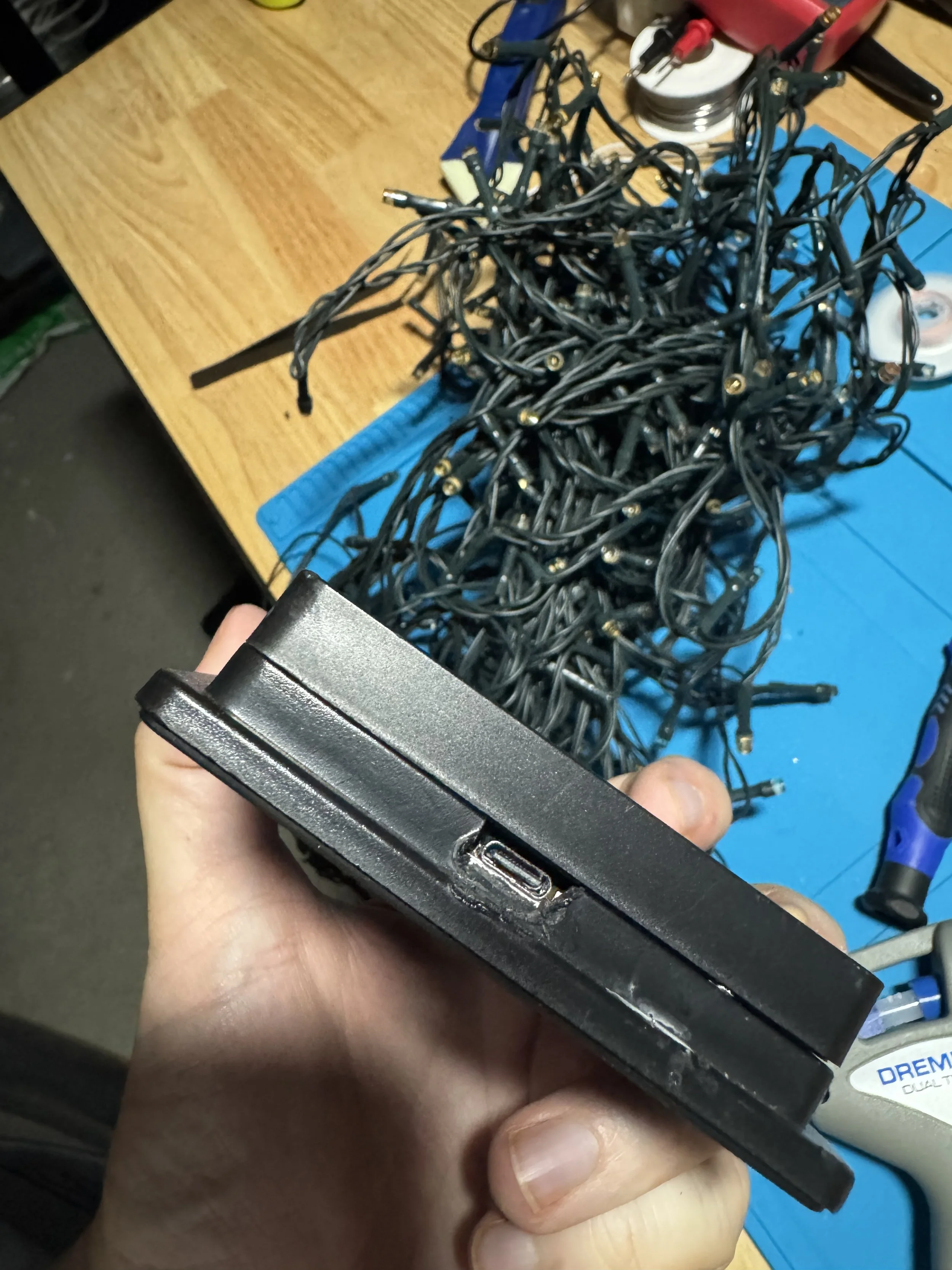
Putting It Back Together
After wiring it up, everything fit back into the original enclosure more neatly than I expected.
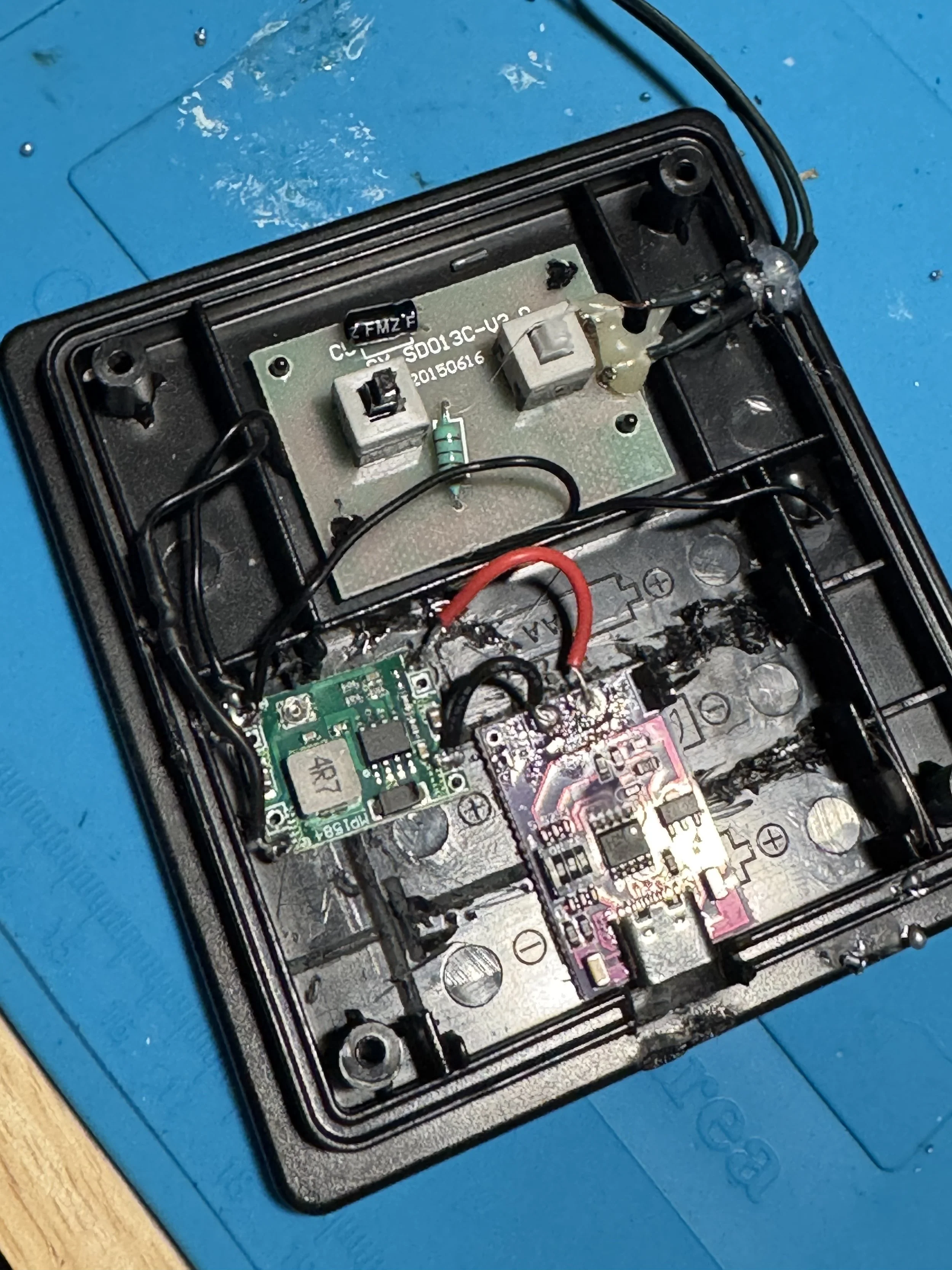
Inside the box now lives:
- a USB-C input cable
- a USB-C trigger board
- a small buck converter
- the original Christmas light controller PCB
The LED string itself is unchanged.
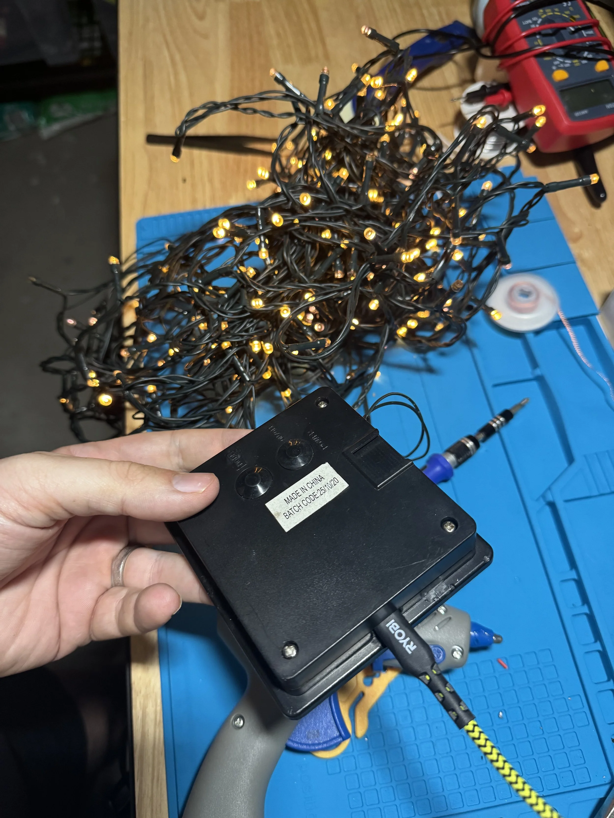
And that was probably my favourite part of the whole thing. I didn’t need to redesign the lights. I didn’t need to understand every detail of the flashing patterns. I just needed to stop the dead power source from being the thing that made the whole device useless.
The controller still runs the same patterns as before.
It’s just getting power from USB now instead of solar plus batteries.
Doing A Very Basic Sanity Check
I don’t have a particularly fancy testing process for this sort of thing, so my approach here was simple:
- Set the buck converter to about 4.0–4.2V
- Run the lights for around 30 minutes
- Check whether the buck converter or controller board gets worryingly hot
Warm felt acceptable.
Too hot to touch would have felt like a sign that I’d misunderstood something.
So far it has all stayed comfortably cool, which is encouraging, although I’d treat that more as “good enough for now” than a grand declaration that the design is perfect.
What I Think I Learned
The most useful takeaway wasn’t really about Christmas lights.
It was that a lot of battery-powered gadgets seem to follow a pretty simple pattern:
power source → controller → load
Once I started thinking in those terms, the project got much easier.
I stopped asking, “How do I rebuild this?” and started asking, “Can I just replace the part that failed?”
In this case, that answer was yes.
And that feels like a nice repair mindset in general: change as little as possible, preserve what still works, and don’t make the project harder than it needs to be.
Things I’m Less Sure About
This is probably the section I would have wanted to read if someone else wrote this up.
A few parts of this worked, but I still wouldn’t claim deep expertise:
- I inferred some of the controller board’s behaviour rather than properly analysing every part of it
- I used a simple heat check rather than measuring everything in detail
- I used the parts I had on hand, not necessarily the most elegant parts for the job
- I haven’t done long-term testing yet
So this feels like a successful experiment, not a definitive guide.
What I’d Do Differently Next Time
A few things stand out in hindsight:
- Measure more upfront. I jumped into assumptions a bit too quickly.
- Use better soldering consumables from the start. That alone would have saved a lot of frustration.
- Document the board more carefully. I took the “close enough” route because the goal was repair, not full understanding.
- Think earlier about enclosure and weatherproofing. USB power is convenient, but it changes how outdoor-safe the original design is.
That said, I’m still glad I did it this way because I learned more by muddling through than I would have by treating it as a neat, solved problem.
What’s Next
The obvious over-engineered next step would be adding an ESP32 and a MOSFET so the lights could be controlled over Wi-Fi or tied into Home Assistant.
That would be fun, although it’s also very much a different project.
For now, I’m happy with the smaller win: a dead gadget works again, I understand it a bit better than I did before, and I got an overdue refresher in soldering.
Key Takeaways
If there’s anything useful here, I think it’s this:
- check the original battery chemistry before assuming the voltage
- replace the failed part before redesigning the whole system
- keep the original controller if it already does something useful
- expect to be worse at soldering than you remember
- treat little repair projects as learning exercises, not tests of competence
And if you’ve done something similar and there’s a cleaner or smarter way to approach it, I’d genuinely love to hear it.
Some photos…